MID-SCALE TEST RIG
This 5 m high (netto) mid-scale FBC test rig fills the gap between the widely available bench-scale and pilot-scale facilities within the scaling up procedure. It is a circulating fluidized bed equipment (CFBC) upon which a wide range of operating points can be set – also including bubbling mode.
Main technical data
| Geometrical dimensions | ||
|---|---|---|
| Riser height (between primary air distributor and chamber top) | 5000 | mm |
| Riser internal diameter | 158 | mm |
| Level of tertiary air inlet | 1900 | mm |
| Level of secondary air inlet | 1300 | mm |
| Height of refractory diffusor | 220 | mm |
| Lower diam. of refract. diffusor | 108 | mm |
| Number of primary air nozzles | 30 | pcs |
| No. of nozzles in the seal pot | 7 | pcs |
| Cyclone internal diameter | 219 | mm |
| Typical operational parameters | ||
|---|---|---|
| Fuel power (@ 11 MJ/kg brown coal) | 80 | kW |
| Temperature (max) | 1000 | °C |
| Superficial gas velocity (max) | 6 | m/s |
| Fuel feed | 8 | g/s |
| Total combustion air | 38 | g/s |
| Secondary & tertiary air (max) | 30 | g/s |
| Primary air (max) | 11 | g/s |
| Electrically preheated air temp. | 200 | °C |
| Bed temp. with gas burner | 600 | °C |
Configuration
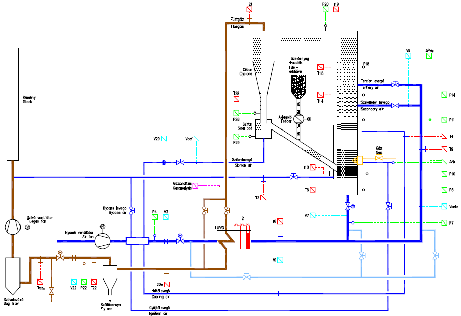
The next figure indicates the configuration of the system in its actual setup. Sample of the flue gas will be delivered to the central gas analyzer of the laboratory in heated line (not indicated on the diagram). Numerous further measuring points are prepared for inserting further sensors.
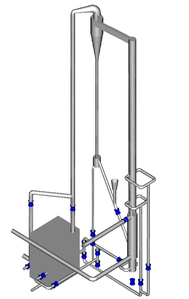
On the next figure, the 3D arrangement of the main components of the mid-scale FBC test rig can be seen.
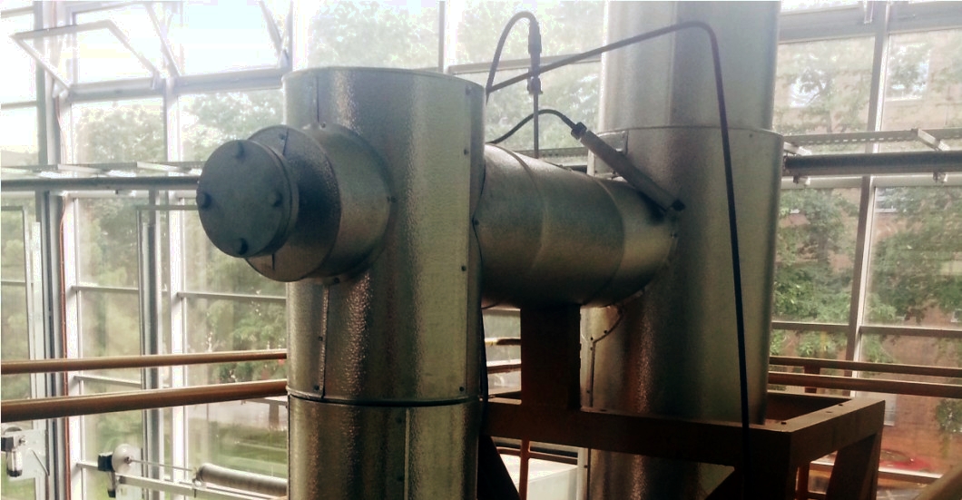
The next photos show some details of the FBC facility – with and still without external heat insulation.
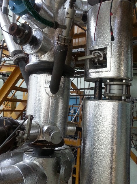
Bottom of the combustion chamber with the return leg, visual observation point and gas burner.
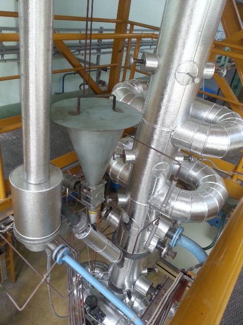
Combustion chamber with secondary and tertiary air inlets.
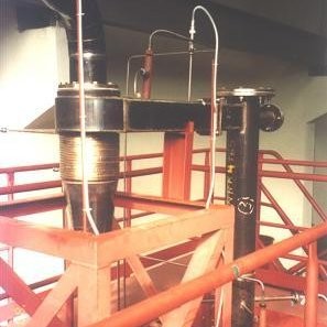
Cyclone and top of the riser with measuring points. Steel structure and podium, 3rd floor.
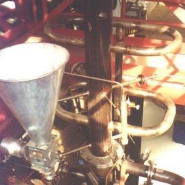
Bunker and feeder for fuel and additives. Combustion chamber with secondary and tertiary air inlets.
Data acquisition & process control system
The FBC test facility is well instrumented for enabling R&D investigations, and there are several free measuring points ready for adapting further sensors for versatile measurements.
The central data acquisition and process control system was recently updated and equipped with a high performance real-time platform capable also for running advanced control algorithms of high mathematical computational demand (PXI by National Instruments).
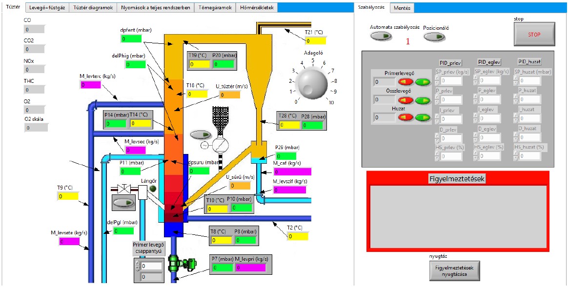
The easily configurable software system allows us easy and fast carrying out of changes on the user interface and background programs, best fitting to the actual research task in order to allow most effective plant operations in all particular cases.
The next figure shows one detail of the standard operator screens.
Typical application areas
- Investigation of the applicability and characteristics of fuels of wide variety
- Coal types and their mixtures
- Low grade and/or high sulfur fossil fuels
- Residue Derived Fuels (including also types still not known by the literature)
- Fuel and additive reactivity
- Combustion profiles
- Bed agglomeration tendencies
- Ash properties (bottom ash & fly ash)
- Deposit formation (easy to dismount and/or endoscopy)
- Investigation of the static and dynamic behaviors of the system
- Development and experimental test of process control strategies
- Education: routine measurement exercises for undergraduate courses.
- Scientific researches on versatile topics (several PhD students involved)
Supplementary investigations
A number of supplementary investigations can be easily carried out by us (or by our qualified partners in some cases). These routine procedures evolved throughout several projects on the mid-scale FBC test rig. The next list gives some examples on them.
Proximate & ultimate analysis
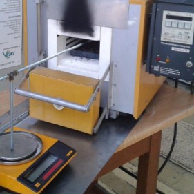
Macroscopic behavior while heating up with TG analysis
Ash composition
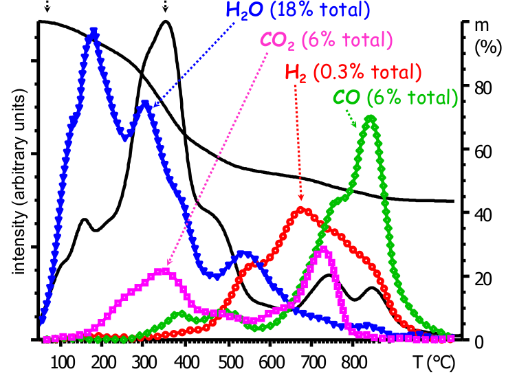
TG-MS analysis
Ash melting procedure
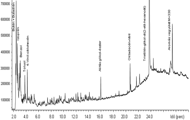
Pyrolysis-GC-MS analysis
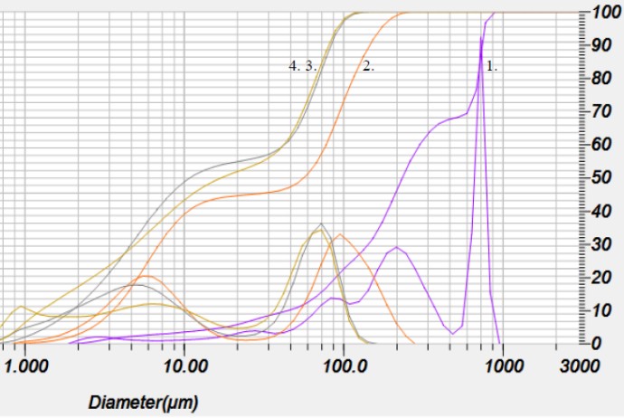
Particle size distribution

Special properties of particular fuel sorts with respect to their applicability in FBCs
Cold fluidization characteristics


